
|
|
|
|
|
|
|
|
|
|
|
|
|


|
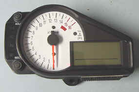
Hopefully this will answer any questions you may have about changing the backlighting colors of your gauge cluster. You can follow these exact instructions to do this on any of the following gauges. Others bikes will be very similar but not exactly the same.
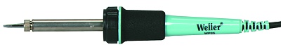
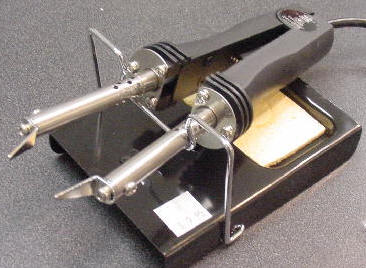
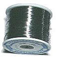
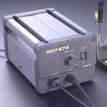
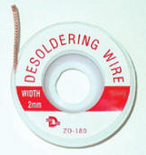
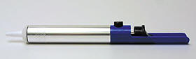
Tools Needed:
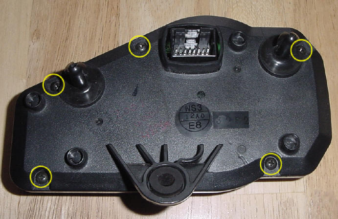
Procedure: Approximate time: 1-2 hours from start to finish Step 1: Remove the gauge cluster from your bike by removing the one screw near the bottom center of the gauges. Then pull the cluster out of it's rubber shock mounts. (Pull straight towards your chest if you are sitting on the bike.) It may be snug but it will come out. Next, depress the locking tab on the wiring harness connector on the back and disconnect the wiring harness. Step 2: Open the case by removing the 5 screws on the back of the case.
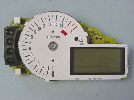
Step 3: Lift the circuit board out of the case. Carefully lift and remove the needle out of the gauges. It may be tough but it will come out. Try not to pry with a screwdriver as this may cause the needle to break. I usually give the needle a counter clockwise twist as I am pulling it out with my fingers. You may want to try 2 spoons to pry the needle out. (If you are replacing the white face, remove the 2 screws immediately above and below the needle.)
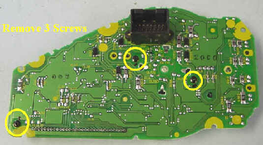
Step 4: Remove 3 screws holding the front lens onto the circuit board
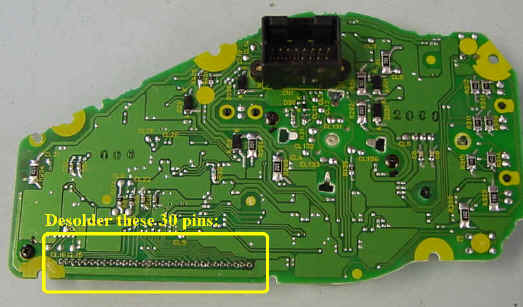
Step 5: De-solder the 30
pins across the bottom. This is necessary to be able to remove the clear lens so
that you can access the LED's. Solder wick is required.
Step 6: Lift clear lens from circuit board
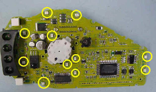
Step 7: Remove the old LED's. This is probably the hardest part. If you have a tweezer iron, that would be the best to use. If you only have a regular iron, try to heat one side and lift it slightly to separate it from the board. Then go to the other side of the LED and it should come off. If not, go back to the first side and start again. Do not apply excessive heat. Solder wick is highly recommended. The wick can pull away excess solder making it easier to separate from the board and it will also clean the solder from the board making it easier to install the new LED's.
Step 7: Install your new
LED's. You will need 11 LED's. (We would like to share the part numbers we use but we can't give away all of
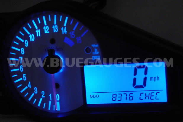
our secrets Step 8: Double check all LED orientations and each solder connection. Do not use too much solder that may short out with other components. Also make sure there is enough solder that the connection is solid and won't crack under vibration. It would be best to inspect all joints with a magnifying glass if you have one. Step 9: Re-insert clear plastic lens with 30 pins and fasten with the 3 screws from the back. Make sure all the leads are through the board and not bent in any way. If you install the screws first, you can be sure the 30 pins will be inserted all the way and will not be placed under stress from tightening the screws later if they were soldered in place already. Step 10: Solder 30 pins to the circuit board. As stated before, do not use too much solder that might cause a short between pins and be sure to use enough so that the joint will not crack under vibration. Again, inspect all joints with a magnifying glass if possible. Step 11: Re-install the needle (and 2 screws for the new faceplate if you are changing it at the same time.) Simply press the needle back into the hole. Step 12: Zero out the needle by turning needle gently counter clockwise until you feel resistance. (Be sure not to hold the needle in as this will allow it to spin freely all the way around.) Then continue until the needle is at the zero position. Step 13: Re-install PCB into case and attach back panel with 5 screws removed earlier. Step 14: Reconnect wiring harness and put back onto your bike. If all goes well, it should then look like this:
Remember, if it is too much
for you to handle, we can do them for you. Our prices include insured return shipping
within the USA and a lifetime warranty for as long as you own the vehicle |